What is link design?
Link design is a process of determining specification of communication architectures to establish link between satellites and ground stations or satellites each other.
Link design repeats determination of specification, calculate link budget and evaluation.
This article explain link design.
How to calculate link budget?
Final goal of lInk design is to calculate link margin.
Link margin is the remainder of substruction of requiring C/N0 from receiver C/N0.
EIRP
EIRP is the abbreviation of equivalent isotropically radiated power or effective isotropically radiated power it describes the power of radio waves.
Supposing \(P_t[\mathrm{dBW}]\) is transmission power, \(L_{ft}[\mathrm{dB}]\) is feed loss of transmission cable, \(G_t[\mathrm{dBi}]\) is the gain of transmission antenna, EIRP is
\[\mathrm{EIRP} = P_t-L_{ft}+G_t\]
Free space path loss
Free space path loss is received atenuation when radio waves pass through free space (imaginary space where no matter exists).
Imaginary space where no matter exists is called free space. Free Space Path Loss (FSPL) is loss when electromagnetic wave pass through free space.
When calculating link budget, there are losses because of atmosphere, rain, polarization, etc. FSPL is the biggest loss in various loss.
Supposing \(d[\mathrm{km}]\) is the distance between antenas, \(\lambda[\mathrm{km}]\) is wave length, \(f[\mathrm{GHz}]\)をis frequency ofr radio wave, free spath path loss \(L_{fsp}\) is:
\[L_{fsp} = 10\log{\left(\frac{4\pi d}{\lambda}\right)^2} = 92.45+20\log{d}+20\log{f} \]
Receiver G/T
Recevier \(\mathrm{G/T}\) is the ratio of receiver gain and system noise temperature, which describes the performance of receiver equipment.
Supposing \(G_r[\mathrm{dBi}]\) is the gain of receiver antenna, \(L_{fr}[\mathrm{dB}]\) is feed loss of receiver cable, \(T_s[\mathrm{dBK}]\) is system noise temperature,
\[\mathrm{G/T} = G_r-L_{fr}+T_s\]
is obtained. Here,
\[T_s = 10\log{(T_{ant}/L+T_f(1-1/L)+T_e)}\]
where \(T_{ant}[\mathrm{K}]\) is antenna noise temperature, \(T_f[\mathrm{K}]\) is feeder noise temperature, \(T_e[\mathrm{dBK}]\) is receiver noise temperature.
Receiver noise temperature \(T_e\) is, using noise factor \(\mathrm{NF}\),
\[T_e = (\mathrm{NF}-1)T_0\]
where \(T_0=290K\).
Receiver C/N0
\(\mathrm{C/N_0}\) is called carrier to noise density ratio, which means the ratio of power of carrier wave to noise power density.
Receiver \(C/N_0\) is, ignoring various losses,
\[\mathrm{C/N_0} = \mathrm{EIRP}-L_{fsp}+G/T+228.6\]
Required Eb/N0
\(\mathrm{E_b/N_0}\) means the ratio of energy per bit to noise power density.
Required \(\mathrm{E_b/N_0}\) is determined based on required bit error rate (BER).
Use following graph.
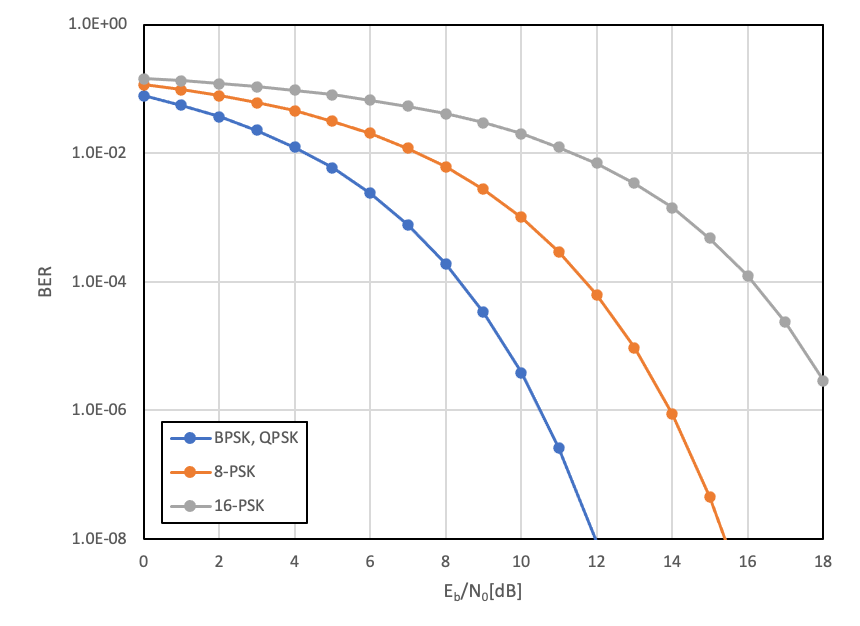
Required \(\mathrm{E_b/N_0}\) varies depending on modulation method.
Typical values of \(\mathrm{E_b/N_0}\) is shown below:
| BER | BPSK,QPSK | 8-PSK | 16-PSK |
| 10-5 | 9.6dB | 13dB | 17.6dB |
Coding gain
Error correction code can improve link margin.
Commonly used coding method and codiing gain are shown below:
| Soft-decision Viterbi decoding | 3dB |
| Hard-decision Viterbi decoding | 5.2dB |
Modulation method
The loss due to modulating the signal is called modulation loss.
This is approximately 3 dB.
Required C/N0
\(\mathrm{C/N_0}\) required for communication is called required \(\mathrm{C/N_0}\).
Supposing \(\mathrm{(E_b/N_0)_req}\) is required \(\mathrm{E_b/N_0}\), \(G_c\) is coding gain, \(L_m\) is modulation loss and \(R\) is data rate, \(\mathrm{C/N_0}\) is:
\[\mathrm{C/N_0} = \mathrm{(E_b/N_0)_req}-G_c+L_m+R\]
Link margin
Link margin equals the remainder of substruction of required \(\mathrm{C/N_0}\) from receiver \(\mathrm{C/N_0}\).